How to Build a Desktop PC (Step by Step for Beginners)
A guide to Phase 1 — Plan a Compatible Parts List, Phase 2 — Assemble the Motherboard, Phase 3 — Fit Everything Into the Case, Phase 4 — Wire, Close and Boot
Building a PC is mostly careful sequencing, not expert electronics. If you can use a screwdriver and follow a checklist, you can assemble a reliable machine in an afternoon. This guide takes you through 37 concrete steps, from confirming that your CPU and motherboard are compatible to the first successful boot into your operating-system installer. We do the delicate work on the motherboard before it goes in the case, so every connector is easy to reach and nothing is forced. Browse all illustrated guides or the Computers and Electronics category for more illustrated walkthroughs on Howcompass.
How do you build a Desktop PC (Step by Step for Beginners)?
 Howcompass | How to Build a Desktop PC (Step by Step for Beginners)
Phase 1 — Plan a Compatible Parts List
HowcompassWrite down what the PC is for
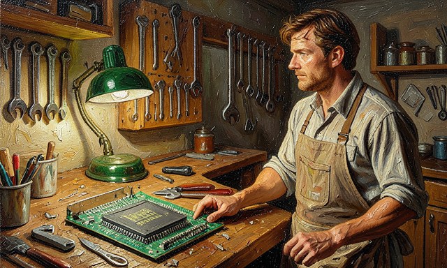
Write down what the PC is for. A gaming rig, a video-editing workstation and a quiet home-office box prioritise different parts. One sentence about the main task decides where the budget goes before you buy anything. For the primary source behind this phase, see Microsoft Support.
 Howcompass
Pick the CPU socket first
Pick the CPU socket first. The processor fixes the socket type, which in turn fixes which motherboards fit. Choose the CPU, then filter motherboards by that exact socket — this is the number-one compatibility trap.
 Howcompass
Match the motherboard chipset and form factor
Match the motherboard chipset and form factor. Confirm the chipset supports your CPU and check that the board size (ATX, micro-ATX, mini-ITX) fits the case you plan to use. Write all three names on the list.
 Howcompass
Choose RAM the board actually supports
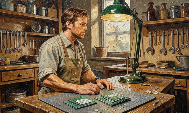
Choose RAM the board actually supports. Check the motherboard spec for DDR4 or DDR5 — they are not interchangeable — and the maximum speed and capacity. Buy a matched kit of two sticks for dual channel.
 Howcompass
Size the power supply with headroom
Size the power supply with headroom. Add the estimated draw of the CPU and graphics card, then choose a reputable supply with about 30–40% spare capacity. Headroom keeps the fan quiet and protects future upgrades.
 Howcompass
Verify the case clears the GPU and cooler
Verify the case clears the GPU and cooler. Compare the graphics-card length and CPU-cooler height against the case's published clearance figures. A few millimetres saved here avoids a part that physically will not fit.
 Howcompass
Lay out every part and screw
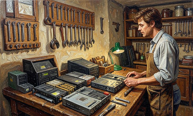
Lay out every part and screw. Unbox everything onto a large table and group the screws by step. Confirm no component is missing before you start, because a mid-build discovery sends you back to the shop. Related on Howcompass: meal prep for a week.
 Howcompass
Set up an anti-static workspace
Set up an anti-static workspace. Work on a hard table, wear an anti-static strap clipped to a grounded metal object, and handle boards by their edges. Static damage is invisible at first and shortens a component's life.
 Howcompass
Read both the board and case manuals
Read both the board and case manuals. Keep the motherboard and case manuals open. They show the exact header positions and standout locations for your specific model, which generic guides cannot.
 Howcompass
Prepare a clean Philips screwdriver
Prepare a clean Philips screwdriver. Use a magnetic Philips head that fits the screws snugly. A loose bit strips screw heads, and a magnetic tip saves countless screws from disappearing into the case.
Phase 2 — Assemble the Motherboard
 Howcompass
Place the board on its box
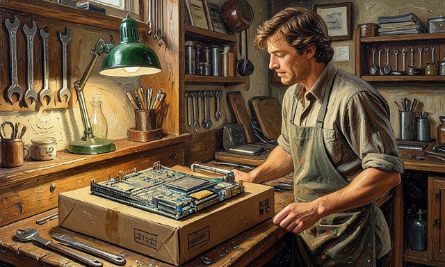
Place the board on its box. Rest the motherboard on the cardboard box it came in, foam-side down. This gives a soft, non-conductive surface and leaves the screw holes clear. For the primary source behind this phase, see Microsoft Learn.
 Howcompass
Seat the CPU in the socket
Seat the CPU in the socket. Lift the socket lever, align the triangle on the CPU with the triangle on the socket, and lower it flat without pressure. If it does not drop in, stop and re-check alignment — never force it.
 Howcompass
Lock the socket lever
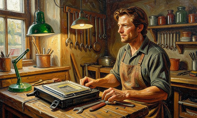
Lock the socket lever. Press the retention arm down gently until it latches under the clip. The processor should sit flush with no visible gap on any edge.
 Howcompass
Install the cooler backplate and bracket
Install the cooler backplate and bracket. Fit the cooler's backplate behind the board and screw on the mounting bracket for your socket. Follow the cooler's own template rather than guessing the standoff pattern. Related on Howcompass: write a research paper.
 Howcompass
Push both RAM sticks into their slots
Push both RAM sticks into their slots. Line up the notch with the slot key and press firmly on both ends until the clips click shut. Seated correctly, the top of each stick sits at exactly the same height.
 Howcompass
Mount the M.2 drive
Mount the M.2 drive. Slide the NVMe drive into its M.2 slot at a slight angle, press it down and secure it with the tiny screw or latch. It should lie flat against the board.
 Howcompass
Plug in the 24-pin and CPU power
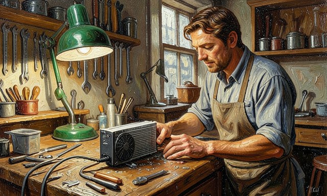
Plug in the 24-pin and CPU power. Connect the large 24-pin ATX cable and the 4+4-pin CPU cable from the power supply. Both click into place; neither should need more than firm, even pressure.
 Howcompass
Attach the cooler and fan cable
Attach the cooler and fan cable. Apply a pea-sized amount of thermal paste if the cooler has none pre-applied, seat the heatsink and plug its fan into the CPU_FAN header. The system will not boot happily without that fan signal.
 Howcompass
Do a bare-minimum boot test
Do a bare-minimum boot test. With the board still on its box, connect a monitor to the onboard video output, short the power-switch pins with a screwdriver, and confirm fans spin and a display appears. Catch DOA parts before the full build.
Phase 3 — Fit Everything Into the Case
 Howcompass
Install the case standoffs
Install the case standoffs. Screw the brass standoffs into the case holes that match your board's form factor, and remove any extras. A stray standoff under the board can short the whole system. For the primary source behind this phase, see Mozilla — web and browser resources.
 Howcompass
Fit the rear I/O shield
Fit the rear I/O shield. Clip the I/O shield into the rear cut-out from inside the case, pressing until it sits flush. Doing it now is easy; doing it after the board is mounted is not. Related on Howcompass: meal prep for a week.
 Howcompass
Lower the board onto the standoffs
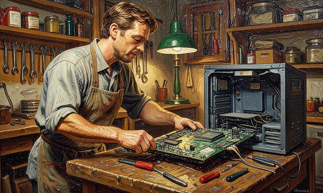
Lower the board onto the standoffs. Tilt the board in so the rear ports pass through the shield, then align every screw hole with a standoff. Do not force a misaligned board — re-check the standoff pattern. Browse all illustrated guides or the Computers and Electronics category for more.
 Howcompass
Screw the board down in a cross pattern
Screw the board down in a cross pattern. Start the screws by hand, then snug them in a diagonal sequence so the board sits evenly. Stop at firm — over-tightening cracks printed circuit boards.
 Howcompass
Slide in any 2.5-inch drives
Slide in any 2.5-inch drives. Mount SATA SSDs or hard drives in a tray or bracket, then secure them with the case screws. Leave a little slack in the cable for vibration.
 Howcompass
Seat the graphics card
Seat the graphics card. Remove the rear slot cover, open the PCIe latch and press the card in until the latch clicks and the bracket screws flat to the case. Support long cards with the supplied brace.
 Howcompass
Install the power supply
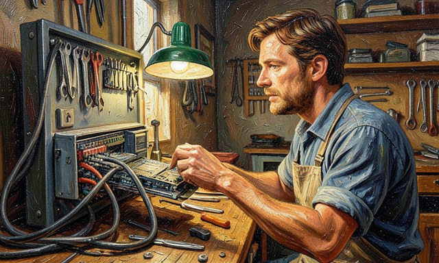
Install the power supply. Slide the supply in fan-side down if the case has a bottom filter, then screw it to the rear chassis. Route the main cables toward the board before tightening it fully.
 Howcompass
Plug the 24-pin and 8-pin back in
Plug the 24-pin and 8-pin back in. Reconnect the two motherboard power cables now that the case is open and spacious. Verify each connector is fully seated before moving on.
 Howcompass
Connect the GPU power leads
Connect the GPU power leads. Attach the required 6+2-pin PCIe cables from the supply to the graphics card. Use separate cables for high-draw cards rather than daisy-chaining one cable. Related on Howcompass: write a research paper.
Phase 4 — Wire, Close and Boot
 Howcompass
Plug in the case fan and RGB headers
Plug in the case fan and RGB headers. Connect case fans to the fan headers and any lighting to the RGB header, matching the 12-volt arrow to the pin marked on the board. Check each fan spins. For the primary source behind this phase, see Apple Support.
 Howcompass
Attach the front-panel header as a block
Attach the front-panel header as a block. If the case uses a combined front-panel connector, plug the whole block onto the F_PANEL header in the corner of the board. Single-pin connectors must match the +/- labels in the manual.
 Howcompass
Connect USB and audio front ports
Connect USB and audio front ports. Plug the USB 2.0, USB 3.x and HD Audio cables into their labelled headers. They are keyed, so check the notch instead of forcing a reverse fit.
 Howcompass
Tidy cables behind the tray
Tidy cables behind the tray. Route cables behind the motherboard tray and secure them with ties, keeping them clear of fan blades. Good airflow starts with cables that do not block it.
 Howcompass
Refit the side panel and connect peripherals
Refit the side panel and connect peripherals. Screw the side panel back on, then plug in the monitor, keyboard and mouse. Plug the monitor into the graphics card, not the motherboard, when a discrete GPU is installed. Browse all illustrated guides or the Computers and Electronics category for more.
 Howcompass
Power on and watch the fans
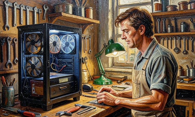
Power on and watch the fans. Switch on the supply and press the case power button. Confirm all fans turn, listen for grinding, and watch that the system posts to the splash screen rather than beeping.
 Howcompass
Enter the BIOS and check temperatures
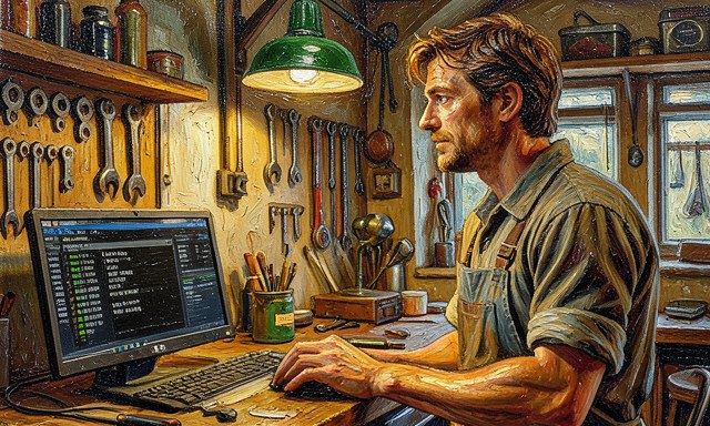
Enter the BIOS and check temperatures. Press the board's delete key to enter setup, confirm the CPU and RAM are recognised at the expected speed, and read the idle temperature. A CPU idling well above 60 °C suggests the cooler is not seated. Related on Howcompass: meal prep for a week.
 Howcompass
Install the operating system from USB
Install the operating system from USB. Boot from a prepared installer USB and follow the operating-system prompts, choosing the new SSD as the target. This clean install confirms the whole build works end to end.
 Howcompass
Update drivers and run a stress test
Update drivers and run a stress test. Install the motherboard and graphics drivers, then run a short CPU and GPU load test while watching temperatures. Stable temps and no crashes mean the build is done.
Frequently Asked Questions
Question: Is building a PC cheaper than buying one?
Often, at the mid-range, and you choose exactly which parts go in. At the very low end, pre-builts can be cheaper because manufacturers buy in bulk; check part-for-part before deciding.
Question: What tools do I actually need?
A magnetic Philips screwdriver, an anti-static strap and a clean table cover almost every step. A small cable-tie kit and a USB installer drive finish the list.
Question: How long does a first build take?
Plan for three to four hours including the OS install, with the manual open. Rushing the wiring is what causes most first-build problems, so keep a break in the middle.
Warnings
- Forgetting the CPU power cable: The 4+4-pin CPU connector is separate from the 24-pin cable and easy to miss. Without it the fans spin but the machine never posts, which looks like a dead board but is simply an unplugged lead.
- Leaving the protective film on the cooler: Many coolers ship with a plastic film over the contact pad. It must be peeled off before mounting; leaving it on traps heat and can push the CPU into thermal shutdown within minutes.
- Forcing a connector backwards: Motherboard headers are keyed, so a connector that will not slide in is usually reversed or aimed at the wrong header. Stop and read the manual — a forced connector bends pins and voids more than one part.
Related Howcompass Guides




References (4)
- Microsoft Supportsupport.microsoft.com
- Microsoft Learnlearn.microsoft.com
- Mozilla — web and browser resourcesmozilla.org
- Apple Supportsupport.apple.com
Sources are listed so you can read the underlying guidance yourself. Our editorial policy explains how guides are reviewed.
Did this article help you?
0 readers found this helpful — add your vote.
No comments yet — be the first to share your results.